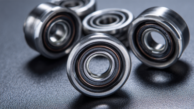
| Bearing construction |
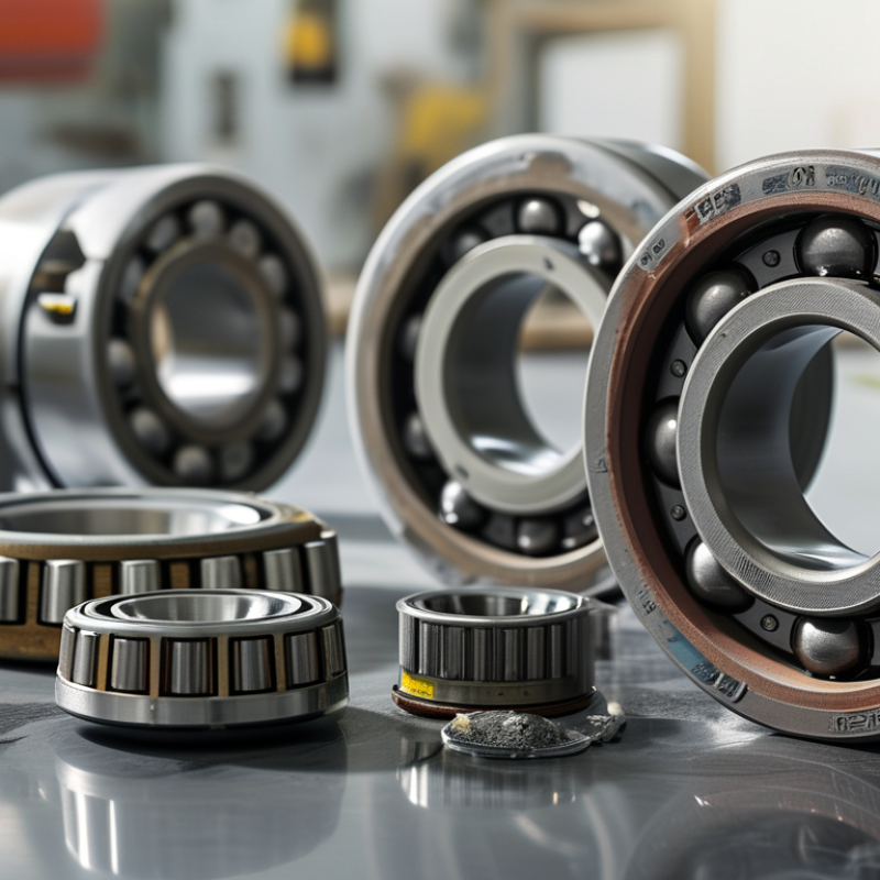
Hybrid bearings use ceramic balls with steel rings. Full-ceramic bearings use ceramic balls and ceramic rings. |
Choose hybrid construction for high-speed, electrically sensitive, or cost-conscious applications. Select full ceramic where corrosion resistance, electrical insulation, or chemical compatibility is essential. |
Confirm ring material, ball material, cage material, load rating, and compatibility with the operating environment. |
| Ball material |
Silicon nitride has a density of approximately 3.2 g/cm³, compared with approximately 7.8 g/cm³ for bearing steel. Its hardness is commonly around 1,500 HV, depending on grade and processing. |
Lower ball mass can reduce centrifugal and gyroscopic forces at high speed. High hardness and wear resistance can improve performance in demanding applications, but do not eliminate raceway fatigue. |
Request material grade, ball-grade classification, surface finish, and inspection documentation. |
| Dimensional precision |
ISO 492 defines dimensional and running-accuracy classes. P0 is the normal class; tighter classes such as P6, P5, P4, and P2 provide progressively stricter tolerances. |
Use P0 for general equipment, P6 or P5 for improved running accuracy, and P4 or tighter only when spindle accuracy, vibration, or positioning requirements justify the added cost. |
Check bore, outside diameter, width, radial runout, and axial runout against the actual shaft and housing tolerances. |
| Internal clearance |
Common radial internal-clearance choices include normal clearance and larger clearances such as C3. The correct value depends on fit, temperature, speed, and load. |
Use normal clearance when shaft and housing fits are moderate and temperature rise is limited. Consider increased clearance when interference fits or high operating temperatures may reduce running clearance. |
Calculate the assembled and operating clearance rather than selecting C3 solely because the application is high speed. |
| Lubrication method |
Grease generally offers simpler maintenance and better sealing retention. Oil provides better heat removal and is commonly used for higher-speed or continuously cooled systems. |
Choose grease for moderate speeds and low-maintenance equipment. Choose oil bath, oil mist, oil-air, or circulating oil when heat generation and speed demand controlled lubrication. |
Confirm lubricant viscosity, base oil, thickener, additive compatibility, minimum start-up temperature, and replenishment interval. |
| Grease fill quantity |
A higher grease fill can improve protection and extend relubrication intervals, but excessive grease increases churning, temperature, and starting torque. |
Use a lower fill for high-speed operation and a higher fill for slower, contaminated, or oscillating applications, subject to the bearing and grease supplier’s limits. |
Record the grease type, fill percentage by free internal space, application speed, and expected temperature. |
| Sealing and shielding |
Open bearings allow relubrication but require external protection. Non-contact shields reduce contamination entry with relatively low friction. Contact seals provide stronger protection but add friction and can limit speed and temperature. |
Use open bearings in clean, controlled housings; shields for clean high-speed environments; and contact seals where dust, moisture, or washdown is the dominant risk. |
Verify seal material, allowable surface speed, temperature range, pressure exposure, chemical resistance, and torque impact. |
| Operating temperature |
Silicon nitride has a coefficient of thermal expansion of approximately 3.2 × 10⁻⁶/K, while bearing steel is commonly about 11–13 × 10−6/K. |
The lower expansion of ceramic balls can reduce thermal effects in hybrid bearings, but ring expansion, lubricant limits, seals, cage material, and preload still determine the usable temperature range. |
Evaluate cold start, steady-state temperature, thermal gradients, preload change, lubricant life, and seal temperature limits. |
| Electrical insulation |
Ceramic components are electrically insulating, while conventional steel bearing components can conduct shaft currents. |
Consider hybrid or full-ceramic bearings for motors, generators, and variable-frequency-drive systems where electrical discharge damage is a risk. |
Determine whether insulation is required through the rolling elements only or through the complete bearing, and verify resistance under operating humidity and voltage conditions. |
| Load capacity and contact stress |
Bearing dynamic load ratings and static load ratings should be evaluated using the applicable ISO bearing-life methods. Ceramic balls do not automatically provide a higher ring load rating. |
Select by calculated radial and axial loads, speed, shock, misalignment, and mounting stiffness. Avoid sizing solely by bore diameter or maximum speed. |
Obtain dynamic load rating C, static load rating C0, limiting speed, axial-load capability, and any derating factors. |
| Rating life |
For ball bearings, the basic rating-life relationship is L10 = (C/P)3, where C is the dynamic load rating and P is the equivalent dynamic load. |
Use the calculated load ratio as a comparison tool, not as a guarantee. Contamination, lubrication, installation, electrical damage, and vibration can dominate actual service life. |
Calculate equivalent load, required reliability, duty cycle, contamination factor, and lubrication condition. Validate critical designs through application testing. |
| Speed capability |
Speed limits depend on bearing size, cage design, lubrication, seals, preload, cooling, and load. There is no universal ceramic-bearing speed rating. |
Compare the application’s continuous and peak speed with the supplier’s grease and oil speed ratings. Reduce speed expectations when using contact seals, heavy grease, or high preload. |
Request reference speed, limiting speed, lubrication-specific speed factor, cage material, preload, and test conditions used for the rating. |
| Cage and retainer material |
Common cage materials include steel, brass, and engineering polymers such as PEEK. Each has different temperature, chemical, speed, and lubricant limits. |
Use a cage material suited to speed, temperature, vacuum, chemical exposure, and acceleration. Polymer cages may reduce mass and noise but require compatibility checks. |
Verify cage clearance, allowable temperature, lubricant compatibility, chemical resistance, and suitability for acceleration or vibration. |
| Installation and fit |
Incorrect fits, impact during mounting, shaft misalignment, and contamination can cause premature fatigue, brinelling, skidding, or seal damage. |
Use controlled heating, proper mounting force through the fitted ring, clean tools, accurate alignment, and the specified shaft and housing tolerances. |
Confirm fit class, shoulder dimensions, runout, mounting procedure, allowable misalignment, and cleanliness requirements. |
| Application risk and validation |
Laboratory ratings cannot fully predict field life because real applications include variable loads, transient speeds, contamination, and temperature changes. |
For safety-critical or high-value equipment, perform endurance, temperature, vibration, noise, electrical-current, and contamination testing under representative duty cycles. |
Define acceptance limits, inspection intervals, vibration thresholds, lubricant analysis requirements, and replacement criteria before production release. |